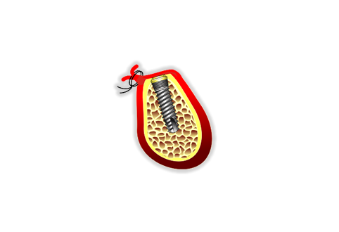
Brief development of the surgical technique for the placement of implant. It consists of the following steps or stages:
Opening drill.
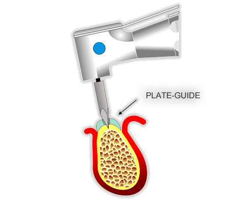
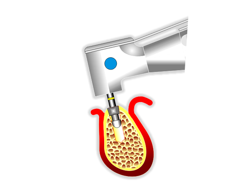
After exposing the bone, a small perforation is made in the bone cortical with the Opening Drill to set a reference point for the guidance and fastening of the next tool.
The drill works with a high speed micro-motor (1000/1500 R.P.M.) and without irrigation and it is necessary to use the guide plate.
Pilot drill of 2.3 mm.
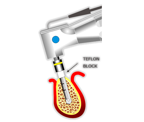
The drill has a 2.3 mm diameter 16 mm length and has laser marks making references to the length of implants (Teflon blocks may be used).
Depth of perforation will be equivalent to the length of implant to be placed.
As in the case of the opening drill, high-speed micro-motor is employed (1000/15000 R.P.M.) with external irrigation.
Note: Check that the flow of irrigation is the adequate to cool the zone.
Teflon Blocks
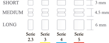
Employed to adjust the perforation depth of drills. The gear contains Teflon blocks for pilot drills of 2, 3 mm and for channeled drills (series 3, 4 and 5), each with three longitudes (short, medium, long).
Pin for parallelization of 2.3 mm.
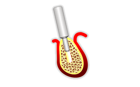 This stage consists in the observation of the direction which provided the pilot drill. For this, the pin for parallelization is placed by its thinner end.
Deepening channeled drills
These drills penetrate into the bone, in order to obtain a cavity with the same length of implant and the same diameter of its nucleus.
The same act with inner irrigation (or combined) with sterile physiological solution with regulated pressure and reduced speed.
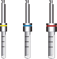
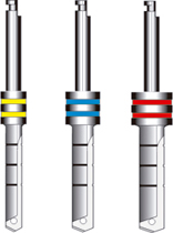
The gear is composed of three channeled drills for implants of series 3, 4 and 5 with a unique length of 16 mm from its active end to its fixed block.
The channeled drills are aimed to cool the surgical area, avoiding bone necrosis produced by the other two drills employed before (opening and pilot drill). It is necessary to employ micro-motor with physiodispenser to carve the bone for the placement of the implant.
These drills are equipped with laser marks which make reference to the length of implants and with a colored ring corresponding to the series.
Procedure
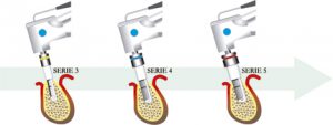
UEmploying the channeled drill Series 3, a perforation equivalent to the length of implant to be placed is made. (Teflon blocks may be used or the laser marks to determine depth).
As from this step, the next one will depend on the series of implant placed.
For implants Series 3, go directly to step 5. Instead, for major diameters implants (series 4, 5 and 6) perforation generated by channeled drill series 3 will have to be increased gradually.
Example: for an implant Series 5 (10 long) the three channeled drills will be employed gradually.
Channeled drills for Compact Bone
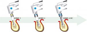
In the case of very compact jawbones, with type D1 bones and some D2, SUPER-MEASURE channeled drills will have to be employed to avoid the bony stress of drilling.
These drills have a major diameter than normal ones and are identified with a “double ring” of the color corresponding to the series. The use of these drills allows employing the self-tapping implant avoiding the forming of threads.
Ejemplo: para un implante Serie 4 (10 de long) en hueso tipo D1/D2 se usaran las primeras dos fresas canalizadas con tope largo en forma progresiva y por último la fresa canalizada HC de la Serie 4.
IMPORTANT:
All drills in and out of bone tissue up
Depth pin:
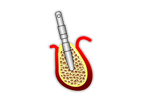 The depth pins have the conical shape of the channeled drills and are marked in 8 mm. 10 mm., 11,5 mm., 13mm. and 16 mm.
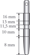
It allows to control if the drill reached the necessary depth so that the head of implant may be situated at the level with the bony tissue after the whole surgical sequence is concluded.
Besides, it allows verifying direction and parallelism of perforation in case it is necessary to make any correction.
Seat drills
The functions of these drills are to widen the cavity in the most external area where the cervical portion (neck) of the implant will be placed.
The gear is composed of different seat drills for each series of implants.
Only the seat drill corresponding to the series of implants which is being placed, has to be used.
It is convenient to employ external cooling and to carry out the procedure at reduced speed.
IMPLANT VEL implant
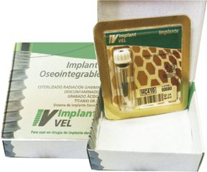
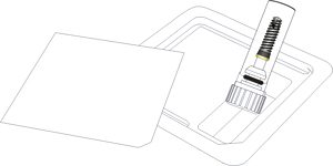
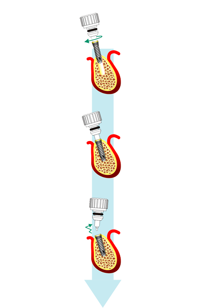 The implant is presented in a closed box which contains the blister protecting the implant system. The assistant will have to open the blister and drop the sterile implant on the operating table.
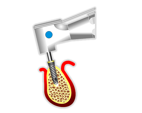
The surgeon picks up the container without touching the implant, taking it through the applicator. Immediately, he has to carry it to the bony site and to screw it until it remains tight. In order to pick up the implant applicator, press slightly on the side and pull softly upwards until the implant is released.
Key for placement of implant
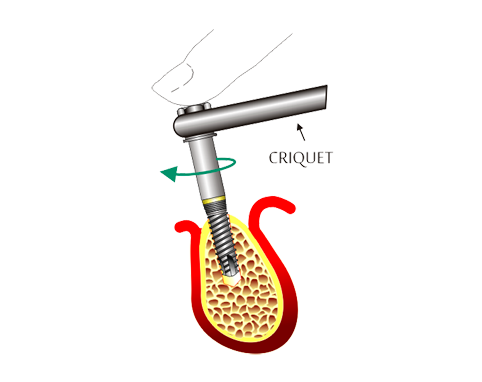 If when screwing with the applicator implant, the same does not reach its final position, it will be necessary to screw by employing the key for placement of implant. In case the adjustment offers resistance (especially in the inferior jawbone), the cricket will have to be used.
Coupling to place implant with micro-motor (optional)
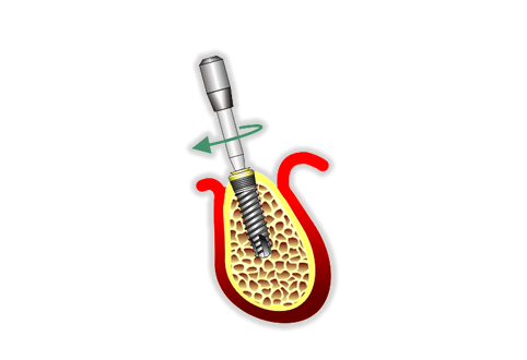
Another option to screw the implant if this did not reach its final position is to use the coupling for micro-motor. In this way, implant may be placed with micro-motor with no need to employ cricket.
Note: You must always verify that the implant is tight in the bone, with no movement at all.
Blockage screw of implant
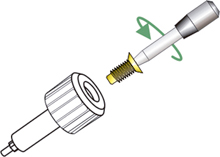
 After placing the implant, its inner thread has to be protected with the blocking screw located in the applicator.
It is placed manually using the screwdriver of the blockage screw and will have to be screwed until it stops.
Stitch
Finally, the surgical site is checked carefully, to detect deshicencies or bony fenestration and after washing with physiological solutions, the soft tissues are stitched.
If necessary, bony fillers and membranes to cover some bone defect must be used.
The adjustment knot of stitch must remain in one of the sides of incision, not over it.

